Pro+ update

Folks

I have had some good news about CE certification and conformance testing. The R&TTE EN 301 783-1 testing has completed successfully, and EMC and safety are being carried out on Wednesday and Thursday this week.

I received the first ten units from the board assembler on Friday afternoon and this has shown up a fault in the device’s own calibration self-testing on some units, although on the comms test set all is good, so the limits need adjusting a tiny bit in the calibration success/fail parameters. A bit weird, because I made up ten units by hand and checked the calibration routine with all ten of those boards, and five of those boards used the exact same parts from the same reels that the assembler’s using.

There’s been just one minor change to the UHF paths and that is to slightly modify the attenuation in a pad that serves both UHF filters: this is a one resistor change, and it’s already in the pick & place machine’s brain. The 70cm path was showing a tad below specification, so I decided to fix it rather than change the specification itself 🙂

I am expecting some more units form the assembler tomorrow (Tuesday 16 October). Assuming these all check out OK, and the CE certification goes according to plan, on Thursday 18 October I will be sending out emails inviting those first who put their names down on the waiting list to “come on down”.

Many thanks, Howard

Posted in Uncategorized | 10 Comments

FUNcube Dongle Pro+ update

Folks,

I’ve just returned from the manufacturer who is starting on the PCB assembly this morning. I hope to have the first units in the next few days assuming all goes well.

I’m still awaiting indications from the conformance testing: that has been going on for ten days now, so I hope to hear very soon.

All being well, assuming production and conformance testing are OK, we’ll be ready to start shipping next week as expected.

Yesterday the final binary image for the firmware was finished, and I spent three hours programming up 500 chips. With a further 1,500 to go, it seems like a thankless task! We normally get them done by the chip manufacturer, but I was concerned about the current worldwide stock of devices a few weeks ago, and with now new new stock not expected until late November, we purchased a couple of thousand (that was all there was!) just in case. Because the firmware wasn’t quite ready at that stage, we ended up having to program the devices ourselves.

While we can program the chips in-circuit after delivery from the manufacturer, this would mean that there is no way for the assembler to check if the board is working. So the chips are preprogammed out of circuit using a special ZIF socket programming adapter, one at a time, with coffee on-hand.

The chips as programmed contain a really neat self-check which can nail down faults to a dozen or so parts. It presents a series of tiny signals at different frequencies into the start of the RF path that tests almost the entire RF section. Internally, it runs an FFT power spectrum against the received signals and compares the results with a known good set of results. If any of the signals are out of specification, the unit flags up an error pointing out where it’s failed, which can then be investigated further.

The many statuses and checks of the FCD are indicated on a single LED inside the unit, using Morse code: sometimes, tried and tested is good!

We have a limit on two parts at present. Firstly, there is a limited number of one of the SAW filters: we have a couple of hundred already with the remainder not due until the end of this month. The other device we are short of is the tuner chip. While there are gazillions on wafer, they still need assembling into packages and then testing. Assembly is happening this week, and I am awaiting a testing schedule. We already have several hundred of these in stock, and I am hoping that the remainder will be available very soon. To make sure of supply in the medium term, we ordered 5,000 units up front.

Many thanks, Howard

Posted in Uncategorized | 5 Comments

Video of FITSAT-1 & FUNcube Dongle Pro+

Folks

This evening I set up a 7″ quarter wave antenna on a baking tray on my balcony connected via 4m of RG-58 coax to a FUNcube Dongle Pro+.

There’s a video of it picking up the FITSAT-1 satellite (launched form the ISS earlier today) here.

Many thanks, Howard

Posted in Uncategorized | 4 Comments

Demo Video of FUNcube Dongle Pro+

Folks

I put together a quick single-take video of the forthcoming FUNcube Dongle Pro + this evening here.

Many thanks, Howard

Posted in Uncategorized | 6 Comments

Announcing the FUNcube Dongle Pro+

Folks

The new FUNcube Dongle Pro+

The new FUNcube Dongle Pro+ offers the following features and enhancements:

o Full coverage of all amateur bands from 136kHz through HF, 6m, 2m, 4m, 2m, 1.25m, 70cm, 33cm, 23cm (150kHz-240MHz and 420MHz-1.9GHz, 70kHz-150kHz coverage through your software’s NCO offset)
o 0.5ppm TCXO
o 192kHz sampling rate
o Eleven discrete front end filters
o Super sharp SAW filters on 2m and 70cm
o No extra device drivers
o Mid October 2012 availability

You can register your interest here, where you’ll receive personal email notification of product availablity.

Many thanks, Howard

Posted in Uncategorized | 70 Comments

FUNcube Dongle Pro+ 2m and 70cm filters

Folks,

I took some pics of the responses of the close-in 2m and 70cm SAW filter responses of the FCD Pro+ tonight, which I show here.

2m Filter response, span 130-160MHz, 10dB/div

70cm Filter response, span 410-470MHz, 10dB/div

Of course, you are still welcome to use the other external discrete LC filters should you decide as an alternative for wider band coverage, although I am sure for most amateur operations, particularly on 2m, the SAW filters will usually be the choice.

Many thanks, Howard

Posted in Uncategorized | 10 Comments

The FUNcube Dongle Pro+: building a PCB with parts on both sides

Old-fashioned 35mm negative storage re-used for SMD parts storage

Folks

The first spin of the PCB for the FCD Pro+ I soldered manually, one part at a time, one side at a time. I used the hot air iron for the big chips, and manually soldered the discretes. Truth is, I knew no better. On speaking to my wonderful assemblers (Holmes Circuit Designs, Letchworth, http://www.hcduk.co.uk), I asked them how they do it without the parts falling off when you turn the board upside down? Now I knew the odd 0402 and 0603 would be safe, with surface tension taking the strain, but what about the heavier parts?

Well there are two ways. Either design the board with the heavy parts on one side, or use a different solder paste on one side to the other, with differing melting temperatures. Preferably, use the first method! Hence, you will see from the earlier pictures, that the FCD Pro+ has the big parts on one side and the relatively smaller parts of the other. Logistically this sounds easier said than done, but in reality with a multilayer board, I found that the number of through vias required limited what you can get away with anyway.

So, when the second PCB spin arrived this time last week, I was eager to try the old pizza oven technique on a double sided board. Sure enough, probably one of the best boards I’ve ever made, first time, no tombstoning (when the part stands up to attention) and no bridges, on either side. Simply load one side, gas mark 6, cool, load other side, gas mark six, cool. Done, as Gordon Ramsay might say.

So that’s great, but turn back the clock an hour or six. What’s the most efficient way of repetitively loading those 250 parts onto a PCB? Answer: use a professional PCB assmebler. Of course, I recommend Holmes Circuit Designs of Letchworth, http://www.hcduk.co.uk, did I mention them already? But what if you’re prototyping, or maybe only doing three or four?

I use a simple paper technique. I print out the parts from the PCB layout, and highlight the positions with a highlighter pen. I do five parts per page. In addition, I keep the parts in order in a folder using old 35mm photo negative storage holders. When you do this, ALWAYS write on the rear of the SMD strips the part’s value. I’ll say that again. ALWAYS write down the value of the SMD part on the back of the strip. That way, when you put the part back in all the excitement, you’ll have some way of knowing when you come back to it that the right part was in the right place.
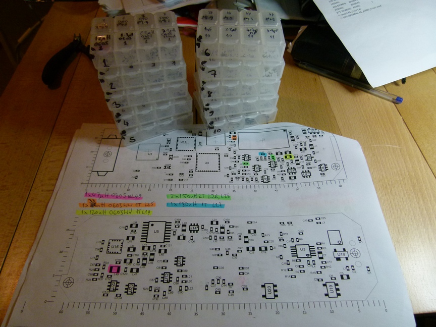
Get your highlighter pens out

If you’re doing more than a couple of boards, accessing the SMD strips one at a time can be a bit time consuming. For quicker access for building multiple PCBs in one shot, I use marked pill box style dispensers for the non-static sensitive devices. Maplin in the UK have a great box for this, http://www.maplin.co.uk/component-storage-box-26133 which has individual _sealed_ lids. Do NOT us component boxes with a single lid for multiple compartments: however hard you try, your 0201 and 0402 parts will cross-mogenate into a chaotic mess that you’ll never fix without having to trash the lot and start again.

To load the compartments, take a sheet of white paper*, and form a seam by folding it in half. Re-open the paper, and empty 50 to 100 parts onto the paper, and use the seam to funnel the parts into the appropriate comaprtment. Use a CD marker to write the part value on the compartment.

When loading up your PCB, if you have a need for, say, a dozen 100nF caps to be loaded onto the pasted PCB, simply empty out enough (+300%) of the 100nF compartment onto a piece of white paper*. Then load up the PCB as per your highlighted notes I mentioned earlier. Then, with the remaining parts on the paper, funnel the remainder back into the compartment.

By the way, always be prepared to lose a few parts: that’s life. Even the best PCB assemblers, such as Holmes Circuit Designs from Letchworth, http://www.hcduk.co.uk, ask for a few extras when their crazy robot machine has had a few too many espressos in the morning. I know exactly how it feels.

Many thanks, Howard

* In line with our ecological aims, the same piece of paper may be used dozens of times for this purpose. Patent not applied for.

Posted in Uncategorized | 1 Comment

Diary of the FUNcube Dongle Pro+, age 2½ weeks

Spaghetti bolognese anyone?

Folks

While we await parts for the original FUNcube Dongle, as you may be aware we’ve taken the opportunity to build an updated version which also has many additional features and performance enhancements.

I am pleased to announce that after several weeks of extensive testing and two PCB spins, we have formally placed an assembly order for the updated FCD, called the FUNcube Dongle Pro+. Also we have a conformance test scheduled for the first week in October. Assuming all goes well, we’ll have units available in mid October, perhaps sooner.

This has been hard work, with many early mornings and late evenings (I had a day job too!) but I am absolutely delighted with the result. For example, each of the eleven front end filters has been tweaked, characterised and tested in situ on the final PCB design, not an easy task as the parts are tiny and getting appropriate VNA connections right on the points of interest was an interesting exercise to say the least.

FUNcube Dongle Mission Control

Unlike my previous development modus operandi, where I tend to throw everything together in one go with minimal unit testing, I chose to unit test _every_ section before integrating onto a single PCB. That in itself meant fabricating about 20 separate prototype PCBs that I made “in the kitchen” you’ll be delighted to hear: I am also pleased to report that luckily, there are no new holes in the stainless steel sink this time. In the short term, unit testing seemed like a lot of extra work, but when it came to integrating, it meant that we _knew_ exactly how everything should behave, and when it didn’t, we knew it should be something easy to resolve.

That held true apart from one small but very significant part. For the band switching, we’re using FET switches rather than band switching or PIN diodes to save on board space and reduce component count. I’d unit tested some specialised high frequency FET SPDT switches for filter switching. These looked fine under unit test: it looked as though if neither FET on each side of the FET was biased, both went open circuit so I could “wire OR” (not the right term, but I guess you know what I mean) several together as a band switch multiplexer.

But when it came to a full test something wasn’t right. Then it was. Then it wasn’t. Hmm… turns out that if the two control voltages on the SPDT switches have no differential voltage, after about 25 seconds the FET switches go into conduction. In the first PCB spin, as a hack, I wrote some code to excercise the switches, by toggling them for 50us every five seconds or so. Not good, but it worked for the remains of my tests until I could get another board spin done.

There were two other interesting but frustrating problems with the MCU I am using. This is supposedly pin compatible with the MCU I used in the old FCD. Well, it is, until you read the silicon errata (or at least read between the lines, one of the faults wasn’t directly addressed, we figured it out ourselves, but not until after hours and hours of head scratching).

Firstly, if you used the I2C interfaces in 400kbps mode, they cause a few GPIO pins unassociated with the I2C interface to pull hard to ground. Secondly, in hard reset, the pin I was using to control the SPI enable for the tuner chip placed the MCU’s oscillator right onto that pin despite being configured otherwise. This would crash the tuner chip, recoverable only with a power cycle.

So, luckily we found these last two out before commiting a PCB spin. I am sure the unit testing has saved at least one, possibly two PCB spins in the end. And at $400 a spin plus four days’ wait for a six-layer board, it was worth it.

Needless to say, the MCU wasn’t really pin-compatible at all. So the PCB is now actually a complete redesign from scratch.

Many thanks, Howard

Posted in Uncategorized | 3 Comments

The FUNcube Dongle Pro+

Folks

While we’ve been out of stock of the original FUNcube Dongle waiting for parts, a couple of months ago we decided to take the opportunity to take into account the feedback by many FCD users with a redesign we’re calling the FUNcube Dongle Pro+. I think that you will find that the results are very worthwhile. There are many enhancements both in performance and features, and I’ll be demonstrating these at the AMSAT-UK Colloquium on September 14-16, 2012, and I highly recommend that you attend if you can!

This is a complete redesign. To give you a flavour, the new FCD has well over twice as many parts in its bill of materials. To cater for this, the board is now a six-layer design (the original FCD was only double sided). To fit these extra parts in, they are soldered on both sides of the PCB. There are no fewer than eleven discrete front end preselection filters, including some serious SAW filters specifically chosen for the 2m and 70cm amateur bands. But that is just the start…

As you can see there is a lot, lot more too, but you’ll have to make it to the AMSAT-UK Colloquium on September 14-16, 2012 to find out just how much can be crammed into a USB stick. (http://www.uk.amsat.org/colloquium/twelve)

I look forward to meeting you!

Many thanks, Howard

Posted in Uncategorized | 32 Comments

Inventory status update

Folks,

I have temporarily run out of FCDs due to a delay in the supply of one of the parts, and my latest information is that the part will be available in August.

I am aware that Martin Lynch has stock currently: http://www.hamradio.co.uk/sdr-software-defined-radio-amsat-uk/funcube/amsat-uk-funcube-dongle-pd-4094.php

We normally manage to get around supply problems by one means or another, and certainly during the earthquake and tsunami last year in Japan, as well as the flooding in Thailand, we had our work cut out in maintaining supply. This time though a quick resolution has proved elusive. I’ll update the site as and when we know anything more.

In the meantime, thank you for your patience!

Many thanks, Howard


Posted in Uncategorized | 2 Comments